

You are using an out of date browser. It may not display this or other websites correctly.
You should upgrade or use an alternative browser.
You should upgrade or use an alternative browser.
Cooling fan continues to run.
- Thread starter EEEnglish
- Start date
Disclaimer: Links on this page pointing to Amazon, eBay and other sites may include affiliate code. If you click them and make a purchase, we may earn a small commission.
crazykid1994
Senior Member
Sounds like a short in the fuse box.
- Joined
- May 19, 2023
- Posts
- 564
- Reaction score
- 773
- Location
- Coastal NE North Carolina
- Ram Year
- 2016 1500 Sport
- Engine
- 5.7 Hemi
Or a stuck closed relay. Not unheard of
crazykid1994
Senior Member
I don’t see how it’s a stuck relay. He claims to have pulled both out and it kept running. The thing I don’t understand is he says he pulled the 60 for the fan and it kept running which makes me wonder if the tipm is melted or if the fan harness is melted somewhereOr a stuck closed relay. Not unheard of
- Joined
- Aug 2, 2018
- Posts
- 19,725
- Reaction score
- 45,067
- Location
- Central Texas
- Ram Year
- 2019 Bighorn, 4 X 4, 3.21 rear, Bright Flame Red Pearl Coat, Mopar tonneau cover,Westin Bed rug
- Engine
- Hemi 5.7
Yeah, makes no sense. If he pulled the relays, stuff should not be running. Something shorted, melted or sumthing,. Gonna take some troubleshooting. He needs to find him a good ole mechanic that knows how to troubleshoot, not a dealership code reader, LOL> All IMHO...I don’t see how it’s a stuck relay. He claims to have pulled both out and it kept running. The thing I don’t understand is he says he pulled the 60 for the fan and it kept running which makes me wonder if the tipm is melted or if the fan harness is melted somewhere
ADDED: On a positive note, at least the fan is running till he can get it in and diagnosed. We used to have to pull the oil cooler fan relay on the Humvee's all the time because the relays would go bad, so we had the oil cooler blowing running 100% of the time (for the Humvee people, remember the relay on the outside cowl just below driver's windshield area, that was the oil cooler relay). . The mechanics were not happy, but without the fan working, burn up the motor on the ole AM Gens.
- Joined
- May 19, 2023
- Posts
- 564
- Reaction score
- 773
- Location
- Coastal NE North Carolina
- Ram Year
- 2016 1500 Sport
- Engine
- 5.7 Hemi
Something doesn't make sense. Unless the TIPM or wiring is shorted together (mouse maybe), or possibly the wrong relay(s) and fuse(s) were pulled, the relay and TIPM circuit boards are the only thing between the fan motor and the battery.
My next move would be grab the old test light and multimeter and start ringing out TIPM and the wiring bundles wiring. Or pulling TIPM and open it up to see if there is any damage inside.
My next move would be grab the old test light and multimeter and start ringing out TIPM and the wiring bundles wiring. Or pulling TIPM and open it up to see if there is any damage inside.
RamDiver
Senior Member
- Joined
- Jan 23, 2022
- Posts
- 2,428
- Reaction score
- 4,244
- Location
- Marlborough, Ontario, Canada
- Ram Year
- 2021
- Engine
- Hemi 5.7
If the fan is still running after pulling the relay, and it is the correct relay, the normally open contact on the relay socket in the TIPM will be energized or...
These fans are often switched by pulling a terminal to ground.
Maybe the smart move now is to verify the vehicle model and the correct schematic drawings to understand how the fan is activated.
And best confirm fuse and relay numbers before dissecting the TIPM.
If the correct fuse and relay were pulled, this suggests a significant wiring or TIPM failure, would this be expected on a 2017 model truck?
.
Last edited:
- Joined
- Aug 2, 2018
- Posts
- 19,725
- Reaction score
- 45,067
- Location
- Central Texas
- Ram Year
- 2019 Bighorn, 4 X 4, 3.21 rear, Bright Flame Red Pearl Coat, Mopar tonneau cover,Westin Bed rug
- Engine
- Hemi 5.7
Not unless something drastic happened, like a meltdown, shorted out TIPM< maybe rodent damage in TIPM (Underneath), hmmmm.If the fan is still running after pulling the relay, and it is the correct relay, the normally open contact on the relay socket in the TIPM will be energized or...
These fans are often switched by pulling a terminal to ground.
Maybe the smart move now is to verify the vehicle model and the correct schematic drawings to understand how the fan is activated.
And best confirm fuse and relay numbers before dissecting the TIPM.
If the correct fuse and relay were pulled, this suggests a significant wiring or TIPM failure, would this be expected on a 2017 model truck?
.
Needs lots of troubleshooting. Because if the proper relays were pulled, no way under normal circumstances should fan be on.
Last edited:
RamDiver
Senior Member
- Joined
- Jan 23, 2022
- Posts
- 2,428
- Reaction score
- 4,244
- Location
- Marlborough, Ontario, Canada
- Ram Year
- 2021
- Engine
- Hemi 5.7
Not unless something drastic happened, like a meltdown, shorted out TIPM< maybe rodent damage in TIPM (Underneath), hmmmm.
Needs lots of troubleshooting. Because if the proper relays were pulled, no way under normal circumstances should fan be on.
But.... if the fan is connected to 12vdc and enabled by a ground to the other terminal and the fan wiring harness were shorted to ground and the wrong fuse was pulled and...
LOL

I think we need a schematic before we're all consumed by the endless possibilities.
When things seem too unusual to be possible, it's time to find the schematic and retrace our initial steps.
.
crazykid1994
Senior Member
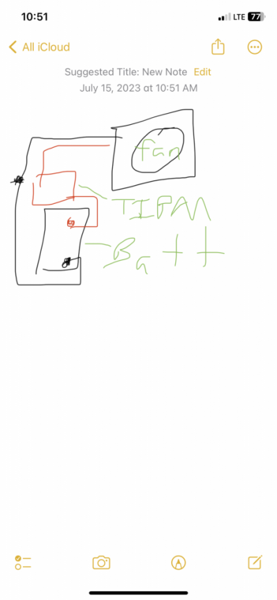
The fan is not enabled by ground. The positive goes through the tipm relays. The positive would have to be shorted. No other way around it. Here’s a crap wiring diagram. as far as I know there are only 2 relays in the tipm for the fan. One marked high speed. One marked low speed. The tipm itself has internal circuit board with wiring that may be shorted between the relays. I think the relays are wired parallel meaning If you short either relay the fan turns on. If the short is internal to the tipm then a new or refurbished tipm will be needed or that one sent out for repair if possible.But.... if the fan is connected to 12vdc and enabled by a ground to the other terminal and the fan wiring harness were shorted to ground and the wrong fuse was pulled and...
LOL
I think we need a schematic before we're all consumed by the endless possibilities.
When things seem too unusual to be possible, it's time to find the schematic and retrace our initial steps.
.
Attachments
RamDiver
Senior Member
- Joined
- Jan 23, 2022
- Posts
- 2,428
- Reaction score
- 4,244
- Location
- Marlborough, Ontario, Canada
- Ram Year
- 2021
- Engine
- Hemi 5.7
The fan is not enabled by ground. The positive goes through the tipm relays. The positive would have to be shorted. No other way around it. Here’s a crap wiring diagram. as far as I know there are only 2 relays in the tipm for the fan. One marked high speed. One marked low speed. The tipm itself has internal circuit board with wiring that may be shorted between the relays. I think the relays are wired parallel meaning If you short either relay the fan turns on. If the short is internal to the tipm then a new or refurbished tipm will be needed or that one sent out for repair if possible.
Wow, FCA is really being cheap with their schematics, it almost looks like an etch-a-sketch drawing.
You have a good memory.
I have no idea of the year of a truck I virtually worked on recently but, I could have sworn this truck always had 12 VDC through the relays and the ECM pulled the other terminal to ground.
The user was confused by measuring 12 VDC on both sides of the fan terminals and yet it wasn't turning. He was not clear on the requirement for a potential difference across the fan terminals versus measuring both wrt to chassis ground.
I can't rule out that I may be mistaken and maybe the 12 VDC was on both sides of the relay and the ECM pulled one terminal to ground, changing the relay state which started the fan. I need a schematic to troubleshoot.
Let's find a real schematic with fuse & relay numbers to be sure we're all on the same page. I found one for the above-mentioned incident.
.
Last edited:
RamDiver
Senior Member
- Joined
- Jan 23, 2022
- Posts
- 2,428
- Reaction score
- 4,244
- Location
- Marlborough, Ontario, Canada
- Ram Year
- 2021
- Engine
- Hemi 5.7
Cooling fan never turns off unless 80a fuse is removed. I can remove both relays and the 60a fuse and leave the key off and it still runs.
Were these the two relays, R1 & R2, that were removed?


And fuse #3 is the 60A fuse that was removed?

Ram 1500, 2500, 3500 (2013-2018) Fuse Diagram • FuseCheck.com
Fuse box diagram (fuse layout), location and assignment of fuses and relays Ram Trucks 1500, 2500, 3500 / Dodge Ram (2013, 2014, 2015, 2016, 2017, 2018).
 fusecheck.com
.
Last edited:
crazykid1994
Senior Member
The new body style v8 sends 12v constant to the fan and uses a signal from the pcm directly to the fan to control the fan. The 2013 and up v6 is the same. 2009-2012 v6 use the 2 relays to turn the fan on. 4th gen v8 use the relays to turn the fan on as well.Wow, FCA is really being cheap with their schematics, it almost looks like an etch-a-sketch drawing.
You have a good memory.
I have no idea of the year of a truck I virtually worked on recently but, I could have sworn this truck always had 12 VDC through the relays and the ECM pulled the other terminal to ground.
The user was confused by measuring 12 VDC on both sides of the fan terminals and yet it wasn't turning. He was not clear on the requirement for a potential difference across the fan terminals versus measuring both wrt to chassis ground.
I can't rule out that I may be mistaken and maybe the 12 VDC was on both sides of the relay and the ECM pulled one terminal to ground, changing the relay state which started the fan. I need a schematic to troubleshoot.
Let's find a real schematic with fuse & relay numbers to be sure we're all on the same page. I found one for the above-mentioned incident.
.
RamDiver
Senior Member
- Joined
- Jan 23, 2022
- Posts
- 2,428
- Reaction score
- 4,244
- Location
- Marlborough, Ontario, Canada
- Ram Year
- 2021
- Engine
- Hemi 5.7
The new body style v8 sends 12v constant to the fan and uses a signal from the pcm directly to the fan to control the fan. The 2013 and up v6 is the same. 2009-2012 v6 use the 2 relays to turn the fan on. 4th gen v8 use the relays to turn the fan on as well.
Thanks for those details.
Where can I plug in my neural interface to embed that data for future reference?
.
rickman57
Junior Member
Not meaning to hijack this thread but I have the exact same issue. I will start a new thread if needed as I'm new on the forum.
2018 Ram 2500 6.4 4x4 170k miles. Recently bought this truck with some issues and still finding more as I fix it. Previous issues were dead battery, cracked radiator and several codes which I chalked up to the battery issue. Once I installed the new battery and radiator, I drove for 30 minutes and all previous and pending codes have cleared except for P0740 which I know relates to TCC. After the test drive, I noticed it was running a little hot (98 degrees outside with AC on). I checked and found the electric fan was not running even though the connector at the fan had power and a good ground so bought a new aftermarket fan and installed it. As soon as I connected the battery, the new fan started running without the key on. I pulled every relay in the TIPM and every fuse (thought as someone mentioned a possible meltdown). The only way to stop the fan from running is to pull the 80 amp fuse (or disconnect the battery). I took the TIPM apart and everything looked fine inside. I traced the main positive feed plate from the positive cable that goes straight to one side of the 80 amp fuse (in addition to other circuits), through the fuse, then to the large single wire connector on the bottom of the TIPM which goes into a wiring harness and out at the connector for the electric fan. I've ohm'd out the wire from the bottom of the TIPM to the connector at the fan, it's the same wire and though it runs through a short harness (2 foot) with other wires, it leaves the harness and runs to the connector at the fan. I don't see any other inline relays from the 80 amp to the fan. I've worked on cars and trucks for 44+ years and this one has stumped me. If I was outside looking in, I would say the same thing some of you are saying. This is impossible. I bought a subscription to alldata and have looked at schematics and diagnostics for days. The schematics show two relays relating to the fan and power going through them in the TIPM but I don't see that on this truck. It also appears no one has attempted any rewiring. Best I can tell neither of the relays in the TIPM tie into the 80 amp fuse which leads to the fan.
I'm thinking the OP and I really don't need anyone telling us this is impossible because I'm telling myself the same thing. What I/we are looking is someone else that has experienced this and what was their fix. Also would be interesting if someone has the time to remove the 80 amp fuse and ohm out the terminal at the fuse to the + side of the fan connector and see if it checks as same circuit. Of course, I will continue working through this and report anything back that I find. Thanks for your thoughts in advance.
- Joined
- Nov 2, 2020
- Posts
- 10,440
- Reaction score
- 13,532
- Location
- El Cajon Calif. 92021
- Ram Year
- 2016
- Engine
- 3.0 ecodiesel
2017 Ram 1500 Wiring ..

2017 Ram 1500 LD Documents
Electrical Wiring Information
Ram Commercial Body Builder Guide - Upfit Your Truck
Ram Trucks Body Builder's Guide has information you need to upfit your truck. Explore the Body Builder Guide for dimensions, electrical & technical guides.
www.ramtrucks.com
2017 Ram 1500 LD Documents
Electrical Wiring Information
- Joined
- Nov 2, 2020
- Posts
- 10,440
- Reaction score
- 13,532
- Location
- El Cajon Calif. 92021
- Ram Year
- 2016
- Engine
- 3.0 ecodiesel
assorted wiring diagrams related to cooling fans Ram trucks
rickman57
Junior Member
Call it Divine intervention, an epiphany, or just a thought I had it on my mind this morning when I woke up. What if someone put a fuse in the slot that wasn't suppose to be there to start with. Maybe F1 as shown in RamDiver's photo of the TIPM isn't suppose to have a fuse. This would make sense as the fan was toast and someone was trying to get the fan to run by installing a 80 A fuse to get it going. Without this fuse in place, it would allow the fan relay to work properly and supply power to the secondary fan as needed. I will test this theory today and report back. Sometimes you look at something so long, you can't see the obvious.
RamDiver
Senior Member
- Joined
- Jan 23, 2022
- Posts
- 2,428
- Reaction score
- 4,244
- Location
- Marlborough, Ontario, Canada
- Ram Year
- 2021
- Engine
- Hemi 5.7
Call it Divine intervention, an epiphany, or just a thought I had it on my mind this morning when I woke up. What if someone put a fuse in the slot that wasn't suppose to be there to start with. Maybe F1 as shown in RamDiver's photo of the TIPM isn't suppose to have a fuse. This would make sense as the fan was toast and someone was trying to get the fan to run by installing a 80 A fuse to get it going. Without this fuse in place, it would allow the fan relay to work properly and supply power to the secondary fan as needed. I will test this theory today and report back. Sometimes you look at something so long, you can't see the obvious.
That's starting to sound like a busy mind inventing solutions to remedy the unknown.
While I can appreciate 'thinking outside of the box', fuse F1 is identified as rad fan control module.
Why would you think the TIPM should not contain this fuse?
.
rickman57
Junior Member
I found another truck just like mine and looked at the fuse box (TIPM). No 80 amp fuse and fan worked fine. Since I replaced my fan, I left the 80 out and went for a drive. Fan kicked on just like it was suppose to without the 80 amp fuse in place. Not sure why Dodge/Ram made it like this unless they use the same TIPM on other vehicles which may use the 80. I consider problem solved. If someone is having cooling/fan problems, I suggest putting in the fuse or at least jumping the 80 terminals. If your fan doesn't come on, tap on the motor and see if it comes on. If so, you know you have a bad fan. I tapped on my old one and it started working. Just for kicks, I took it apart and found the brushes were shot. I guess you could replace the brushes but did not look like an easy job with the way the motor is made. Thanks for the help and comments.
Similar threads
- Replies
- 2
- Views
- 2K
- Replies
- 0
- Views
- 276